2 30; 1.2.4 operation of the product can be made by one operator from among electricians, examine the document, trained in the practical work with the product, and having a group of safety in installations with a voltage over 1,000 V not less than the third & nbsp;.
& nbsp;
1.3 specifications
1.3.1 IPI-100 It provides in normal conditions of use measurement tangent tg & delta dielectric loss; and measuring the capacitance Cx of objects in the ranges and the main measurement error below:
A range measuring dielectric loss tangent of 5 10-4 to 0,3;
-limit permissible absolute basic error in the measurement of the dielectric loss tangent for the total capacitance of the measuring range of the test voltage at a frequency of:
50 Hz + (5. 10-4 + 0,05 tg & delta;)
54 Hz + (1. 10-3 + 0,13 tg & delta;)
measurement range at the test voltage capacitance:
100 kV from 5 pF to nF 3;
50 kV from 6 pF to 10 nF;
- maximum permissible basic error in measuring the capacitance at the frequency:
0.5 pF 50Hz Cx + 0.03 < / p>
54 Hz 0.5 pF Cx + 0.04;
- measuring the voltage range of 10 to 100 kV;
- maximum permissible relative error in the measurement of RMS voltage at a frequency of:
50 Hz +3%;
54 Hz +3%
Note: The meter will convert the dielectric loss tangent, and. . Measurements at the frequency of 54 Hz to 50 Hz
1.3.2 limit of tolerable additional measurement error caused by changes in ambient temperature from normal (20 & plusmn; 5 & deg; C) to either within the working area, does not exceed half the maximum permissible primary measurement error (n. 1.2.2) for every 10 degrees. . Temperature changes
1.3.3 FPI 100 allows the measurement of & laquo; direct & raquo; and & laquo; inverted & raquo; measurement schemes that provides a measure of insulation objects parameters as with isolated or grounded pin.
1.3.4 IPI-100 provides the output of measurement results on the liquid crystal display (LCD) display unit. Communication between the measurement unit and the display unit is carried on a radio channel in the frequency range 845-945 MHz. Stability of the radio at a distance 5-7 m level is provided in transmitter output power of 1 mW.
1.3.5 Image numbers and symbols on the display distinguishably at least 0.8 m at an external illuminance of 10 to 1,000 lux .
1.3.6 IPI-100 under normal operating conditions and the application is ready to operate for no more than 1 minute after switching.
1.3.7 Duration of operation is determined by power consumption meter used electrochemical accumulators . When the battery capacity of 1800 mA & bull; h duration of at least 10 h
1.3.8 MTBF for the operating conditions of application of at least 4000 h
1.3.9 average period.. service meter & ndash; at least 8 years.
1.3.10 Dimensions and weight of the meter components shown in Table 1.
1.4 Completeness
IPI-100 supplied completeness, specified in table 1.
table 1 №
Name
part
designation
Max
dimensions, mm
Weight, < p> kg
Note
| 1 | unit HV < / td> | IPI-100-BV | 1 | & AElig; 240 x 800 | 5 | & nbsp; |
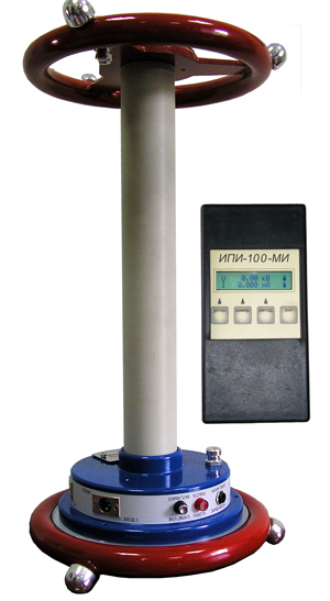
| 4 | display module | IPI-100MI | 1 < / p> | 90h186h42 | 0,3 | & nbsp; |
| 5 | The voltage sensor | FPI -100DN | 1 | & AElig; 680 x 500 | 3 | & nbsp; |
| 6 | The charger | 9- 12B, 300-900 mA | 2 | & nbsp; | & nbsp; | & nbsp; |
| 7 | Set of measuring cables: & nbsp; | IKE-1 IKE
-3
IKE-10 |
1 2
1 | & nbsp; | & nbsp; | & nbsp; < / tr> |
| 8 | Measuring the insulation value IPI-100. Manual operation IPI-00.00.00RE | IPI-100 00.00.00RE | 1 | & nbsp; | & nbsp; | & nbsp;
Terms and Conditions Shipping and payment Warranties & Returns Contacts
Documentation for download of the device not available
|