1.1 Assignment device 1. Voltage divider D & ndash; 140, D-140.00.00.00, (hereinafter - the divisor) is designed to measure the alternating voltage of 100 kV and a DC voltage to 140 kV with an electronic digital voltmeter having an input impedance of 10 Mohm
. possible to use digital multimeters type M890G, DT890B +, DT9207A etc.
1.1.2 divider designed for use indoors in a temperature range from 10 0 C to +35 0 C, the relative air humidity up to 80% and a pressure of from 650 to 800 mm Hg.
1.1.3 on site installation is not permitted shaking, vibrations, the presence of air in the aggressive fluids (acids, alkalis, etc.).
1.2 Main technical data Table 1
Name of the parameter
The parameter
| 1. Division factor | 10000 & plusmn; 50 |
| 2. The range of measured DC voltage, kV | 1 & ndash; 140 |
| 3. Range of measured voltages AC frequency of 50 Hz (effective value), kV | & nbsp; 1 & ndash; 100 |
| 4. Dimensions of the high-voltage unit, mm | & Oslash; 200 & times; 1000 |
| 5. Weight of a high-voltage unit, kg, more | 6 |
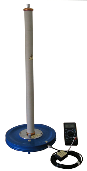
| 6. a DC voltage measurement relative error given (with voltmeter DT890B + at the limit of 20 V) | & plusmn; 1,5% < tr> | 7. Reduced relative measurement error of the AC voltage (with a voltmeter DT890B + at the limit of 20 V) | & plusmn; 2,5% < / table> Note: precious materials in the product are missing 1.3 Configuration & nbsp; 1.3.1 Set. delivery divider shown in table 2. table 2 designation Name Number of. Note: | D-140.10.00.00 | The block HV | 1 | & nbsp; | | D-140.10.80.00 | The cable measuring | 1 | Length 5.5m | | DT890B + | Digital multimeter | 1 | & nbsp; | | D-140.00.00.00RE | User Manual | 1 | & nbsp; 1.4 Construction and operation of the product & nbsp; 1.4.1 Schematic diagram of the divider shown in Fig.1 divider circuit is formed by an ohmic voltage divider, and belongs. from block high A1 and measuring cable with built therein switchable load A2. high-block consists of 16 resistors R1-R16 PE-10kV-68M, connected in series in a high shoulder and a resistor R17 (1M) in the low voltage leg. The input impedance is equal to the high-voltage unit 1088 & plusmn; 100 MOhm dividing ratio -1000 & plusmn;. 100 (at the disconnected cable measurement) DN.10.80.00 measuring cable is made on the basis of the radio-frequency coaxial cable RG58-C / U. A built into it comprises load resistors switchable tumbler S1 & quot; VOLTAGE & quot ;. The presence trimmers R20, R21 allows you to adjust the division factor separately on DC and AC voltage. Adjustment is made by rotating the axes trimmers through openings in the side wall of the load body Conclusions terminated with loading forks: X4 (potential) & ndash;. red, X5 (shared) & ndash; . Black The appearance of the divider shown in Figure 2 1.5 Labeling & nbsp;. 1.5.1 The body divider plate attached & laquo; voltage divider D-140. Block the high-voltage D-140.10.00.00 & raquo ;, number, year 1.5.2 At the load applied to the measurement cable labeling & laquo;. D-140.10.80.00 & raquo;. 2 Notes security 2.1 to work with a divider allowed persons with group safety in installations with a voltage above 1000 V is not lower than the third. 2.2 The case of the high-block divider must be grounded, and the operator station must be equipped with an insulating base & ndash; rubber mat with a dielectric, a group of I GOST 4997-75. Other safety measures regulated by the Rules for Electrical / Energy devices SSSR., 6th ed., rev. and Sub-M .: Energoatomisdat, 1985.-640c.
Terms and Conditions Shipping and payment Warranties & Returns Contacts
Documentation for download of the device not available
| |