Specify the price Availability: under the orderCondition: new
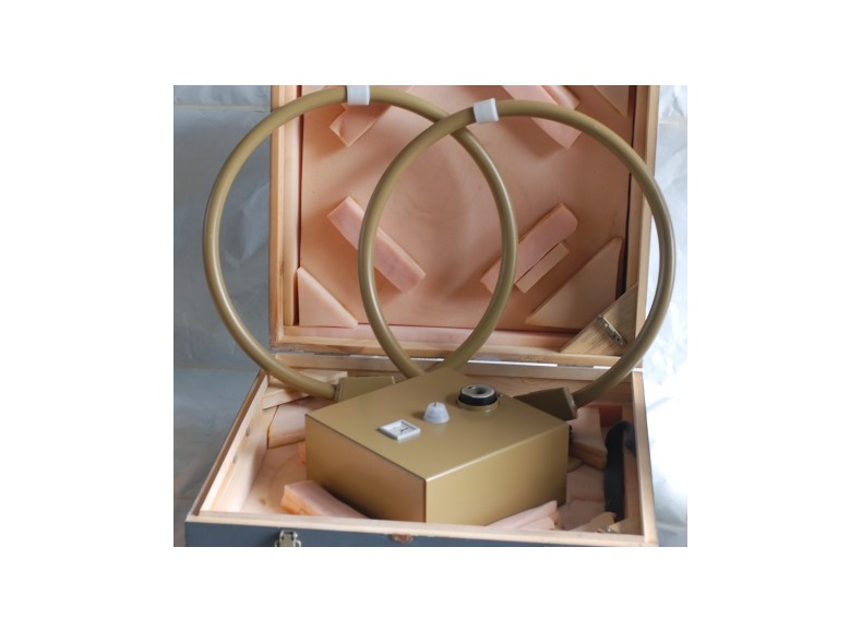
The voltmeter selective & nbsp; FMA11 & nbsp; is & nbsp; for measurement of the field strength is a combination of loop and whip antenna and & nbsp; for the frequency range 0,009MGts to 30MHz
Specifications of the device & nbsp; FMA11.: & nbsp;
View antenna & nbsp; & mdash; the combination of the frame and the vertical whip antenna, a converted sampling equipment unit for setting a frame antenna or antenna pin; The number of aerial frames & nbsp; & mdash; 2; The characteristics of the antenna pin & nbsp; & mdash; a pin with a fixed length; Frequency range FMA11 & nbsp; & mdash; & nbsp; 0,009MGts from 30 MHz subband division in two overlapping; Selectable sub-bands for the framework and the whip antenna and associated antenna frame:
& nbsp;
antenna frame 1 < / td>
antenna frame 2
0,009MGts-0,021MGts
1.6 MHz-4,01MGts
0,02MGts-0,041MGts
4,0MGts-10,01MGts
0,04MGts-0,081MGts
10,0MGts-17,51MGts
0,08MGts-0,151MGts
17,5MGts-30,0MGts
0,15MGts-0,31MGts
& nbsp; & mdash;
0,30MGts-0,61MGts
& nbsp; & mdash;
0,60MGts-1,61MGts
& nbsp; & mdash;
& nbsp;
Switching frequency subbands & nbsp; & mdash; automatic shift control executed selective microvoltmeter type & nbsp; SMV 11 & nbsp; via connecting cable depending on the set frequency of the receiver; Directional characteristic FMA11: & nbsp;
& mdash; loop antenna: The horizontal radiation pattern of & nbsp;
& mdash; corresponds to the diagram & nbsp; orientation magnetic field;
symmetry (the ratio of maximum to minimum voltage in the receiver th & shy; rizontalnoy directivity pattern) & nbsp; & mdash; & Gt; 20dB;
& nbsp; & mdash; Whip Antenna: The horizontal radiation pattern of & nbsp;
Setting the direction of reception of the loop antenna & nbsp;
& mdash; by hand by turning the frame on the device to configure; Fitting Range & nbsp; & mdash; smoothly from 0 & ordm; to 360 & ordm ;;
Indication & nbsp; & mdash; graduated scale division 5 & deg ;; Output parameters FMA11: nominal value of the output resistance & nbsp; & mdash; & nbsp; Z = 50cm; Reflectance & nbsp; & mdash; | R | & le; 0,33;
Connection type & nbsp; & mdash; & nbsp; HF socket 3/7 (two separate outputs for the framework and the pin antennas); Features field strength measurement & nbsp; FMA11: Value field & nbsp; & mdash; obtained in dB (uV ∙ m-1 & nbsp; as the sum of the values of measured voltages in dB / uV / a matched antenna output and the correction coefficient K [dB (m-1)] which depends on frequency;
Correction factor :
& nbsp; calibration conditions:. & nbsp; & mdash; loop antenna & nbsp; & mdash; K coefficient is valid for maximum directivity characteristic (the main direction of reception) calibration implemented normal field known field intensity: E = Zo ∙ H (Zo = 377 ohms), E [dB (uV ∙ m-1)] = H [dB (uV ∙ m-1)] + 51,5dB; & nbsp;
& mdash; whip antenna & nbsp; & mdash; factor It holds for the measuring device soglasnoCISPR-release 1A (for calibration in the near zone of: joint arrangement of the antenna and the receiver on the metal table area 1h1m and enabling the antenna base height of 1.2 m in height) ratio Target & nbsp; & mdash; through adjustments tables caused instance and incoming & nbsp; in the delivery of each antenna, for the field intensity; Guaranteed values FMA11:
coefficient K at selected frequencies
loop antenna
Whip Antenna
10kHz
62,2dB & plusmn; 1dB
59,8dB & plusmn; 1dB
400kHz
45,0dB & plusmn; 1dB
43,0dB & plusmn; 1dB
30MHz
29,8dB & plusmn; 1dB
13,0dB & plusmn; 1dB
minimum measured field strength on the selective microvoltmeter & nbsp; SMV 11 & nbsp; & mdash; is obtained as the sum of the minimum measured & nbsp; voltage U & nbsp; [dB (uV)] on selective microvoltmeter & nbsp; SMV 11 & nbsp; for a strip of appropriate width and type of indication, as well as frequency-coefficient K [dB (m-1)], which select the calibration field intensity table; Typical values for selected frequencies: & nbsp; & mdash; Display view AV 1, sinusoidal signals, additional measurement error due to self-noise
& nbsp;
& le; 1dB
loop antenna
whip antenna
9 kHz, B = 200Hz
53dB = 450mkV / m
50dB & nbsp; = 320mkV / m
150 kHz, B = 200Hz
31dB = 35mkV / m
= 27dB 22mkV / m
30MHz, B = 200Hz
= 10dB 3,2mkV / m
& nbsp; & mdash; 7dB = & nbsp; 0,45mkV / m
& nbsp; & mdash; view indicating Qr, sinusoidal signals, additional measurement error due to self-noise
& le; 1dB
loop antenna < td> whip antenna
9 kHz and B = 200Hz
53dB = 450mkV / m
50dB = 320mkV / m
150 kHz, V = 200Hz
36dB = 63mkV / m
32dB = 40mkV / m
150 kHz, V = 9 kHz
49dB = 280mkV / m
46dB = 200mkV / m
30MHz, The 9kHz =
= 30dB 32mkV / m
= 13dB 4,5mkV / m
Most measured field intensity FMA11: & nbsp ; & mdash; view indicating AV 1
sinusoidal signals
loop antenna
whip antenna
9 kHz-30 MHz B = 200Hz
130dB = 3,2V / m
130dB = 3,2V / m
& nbsp; & mdash; view display Qr
sinusoidal signals
loop antenna
Whip Antenna < tr>
9 kHz-150 kHz = 200 Hz In
130dB = 3,2V / m
130dB = 3,2V / m
150 kHz-17,5MGts B = 9 kHz
130dB = 3,2V / m
130dB = 3,2V / m
17,5MGts-B = 30MHz 9kHz
130dB = 3,2V / m
120dB = 1V / m < p> & nbsp;
The measurement error of the field strength of the antenna & nbsp; FMA11 together on selective microvoltmeter type SMV 11 & nbsp; (in the operating mode & quot; whip antenna & quot; only for the measuring device 1A issue); Basic error at a value of reflectance of the receiver input impedance | r | & le; 0,1 (high frequency attenuation of & ge; 10 dB) and at 23 & deg; C & plusmn; 2 & deg; C & nbsp; & mdash; & Plusmn; 2,0dB; Accuracy of temperature & nbsp; & mdash; & Plusmn; 0,3 dB / 10 & deg; C; Additional error at a value of reflectance of the receiver input impedance | r | & le; 0,33 & nbsp; & mdash; & Plusmn; 1,0dB; Power FMA11: Protective low voltage from the selective microvoltmeter type & nbsp; SMV 11 & nbsp; & mdash; 15V-0.5V; Power consumption & nbsp; & mdash; 1W; The control signals for switching frequency bands: Signal Type: & nbsp; & mdash; binary coded control signal 4 bits in parallel; Signal level & nbsp; & mdash; lower from 0V to 2V from 13V to upper 15B; Running time FMA11: & nbsp; & mdash; & nbsp; for electronic modules & nbsp; & mdash; continuous operation subject to climatic conditions of operation; Ambient temperature range & nbsp; & mdash; & nbsp; & mdash; 25 & ordm; C ... + 45 & deg; C; Related extreme values in natural environments (temperature / humidity) & nbsp; & mdash; + 30 & ordm; C / 95%; Rated wind speed when installing the tripod FMA11 SMV 11 & nbsp; and a height of 1.2m antenna base & nbsp; & mdash; & Le; 60km / h, without special measures, to 120km / h with the further strengthening the tripod legs to ground surface; Dimensions: The device to adjust the & nbsp; & mdash; 325h325h200mm; frame diameter of & nbsp; & mdash; 600mm; The length of the antenna pin & nbsp; & mdash; 1m; Weight: Device for setting the frame 2, the antenna pin & nbsp; & mdash; 14kg.